[库]一些常用的模块例程和资料库
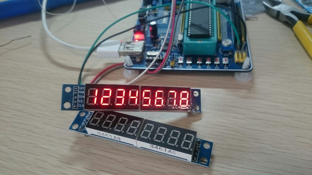
MAX7219数码管显示控制模块
MAX7219是一种集成化的串行输入/输出共阴极显示驱动器,它连接微处理器与8位数字的7段数字LED显示,也可以连接条线图显示器或者64个独立的LED。其上包括一个片上的B型BCD编码器、多路扫描回路,段字驱动器,而且还有一个8*8的静态RAM用来存储每一个数据。只有一个外部寄存器用来设置各个LED的段电流。
一个方便的四线串行接口可以联接所有通用的微处理器。每个数据可以寻址在更新时不需要改写所有的显示。MAX7219同样允许用户对每一个数据选择编码或者不编码。
整个设备包含一个150μA的低功耗关闭模式,模拟和数字亮度控制,一个扫描限制寄存器允许用户显示1-8位数据,还有一个让所有LED发光的检测模式。
只需要3个IO口即可驱动8位数码管。数码管显示时无闪烁。支持级联。
代码示例
单连
#include <reg52.h>
#define uchar unsigned char
#define uint  unsigned int
//定义Max7219端口
sbit Max7219_pinCLK = P1^2;
sbit Max7219_pinCS  = P1^1;
sbit Max7219_pinDIN = P1^0;

void Delay_xms(uint x)
{
 uint i,j;
 for(i=0;i<x;i++)
  for(j=0;j<112;j++);
}
//--------------------------------------------
//功能:向MAX7219(U3)写入字节
//入口参数:DATA
//出口参数:无
//说明:
void Write_Max7219_byte(uchar DATA)
{
        uchar i;
        Max7219_pinCS=0;
        for(i=8;i>=1;i--)
          {
            Max7219_pinCLK=0;
            Max7219_pinDIN=DATA&0x80;
            DATA=DATA<<1;
            Max7219_pinCLK=1;
           }
}
//-------------------------------------------
//功能:向MAX7219写入数据
//入口参数:address、dat
//出口参数:无
//说明:
void Write_Max7219(uchar address,uchar dat)
{
     Max7219_pinCS=0;
     Write_Max7219_byte(address);           //写入地址,即数码管编号
     Write_Max7219_byte(dat);               //写入数据,即数码管显示数字
     Max7219_pinCS=1;
}

void Init_MAX7219(void)
{
 Write_Max7219(0x09, 0xff);       //译码方式:BCD码
 Write_Max7219(0x0a, 0x03);       //亮度
 Write_Max7219(0x0b, 0x07);       //扫描界限;4个数码管显示
 Write_Max7219(0x0c, 0x01);       //掉电模式:0,普通模式:1
 Write_Max7219(0x0f, 0x01);       //显示测试:1;测试结束,正常显示:0
}
void main(void)
{
 Delay_xms(50);
 Init_MAX7219();
 Delay_xms(2000);
 Write_Max7219(0x0f, 0x00);       //显示测试:1;测试结束,正常显示:0
 Write_Max7219(1,8);
 Write_Max7219(2,7);
 Write_Max7219(3,6);
 Write_Max7219(4,5);
 Write_Max7219(5,4);
 Write_Max7219(6,3);
 Write_Max7219(7,2);
 Write_Max7219(8,1);
 while(1);
}
级联
#include <reg52.h>
#define uchar unsigned char
#define uint  unsigned int
//定义Max7219端口
sbit Max7219_pinCLK = P0^2;
sbit Max7219_pinCS  = P0^1;
sbit Max7219_pinDIN = P0^0;

void Delay_xms(uint x)
{
 uint i,j;
 for(i=0;i<x;i++)
  for(j=0;j<112;j++);
}
//--------------------------------------------
//功能:向MAX7219(U3)写入字节
//入口参数:DATA
//出口参数:无
//说明:
void Write_Max7219_byte(uchar DATA)
{
        uchar i;
        Max7219_pinCS=0;
        for(i=8;i>=1;i--)
          {
            Max7219_pinCLK=0;
            Max7219_pinDIN=DATA&0x80;
            DATA=DATA<<1;
            Max7219_pinCLK=1;
           }
}
//-------------------------------------------
//功能:向MAX7219写入数据
//入口参数:address、dat
//出口参数:无
//说明:
void Write_Max7219(uchar address,uchar dat)
{
     Max7219_pinCS=0;
     Write_Max7219_byte(address);           //写入地址,即数码管编号
     Write_Max7219_byte(dat);               //写入数据,即数码管显示数字
     Max7219_pinCS=1;
}
//-------------------------------------------
//功能:向第二片MAX7219写入数据
//入口参数:address、dat
//出口参数:无
//说明:
void Write_Max7219_2(uchar address,uchar dat)
{
     Max7219_pinCS=0;
     Write_Max7219_byte(address);           //写入地址,即数码管编号
     Write_Max7219_byte(dat);               //写入数据,即数码管显示数字
     Max7219_pinCLK=1;
     Write_Max7219_byte(0X00);              //对第一片执行空操作
     Write_Max7219_byte(0X00);
     Max7219_pinCS=1;
}
//MAX7219初始化
void Init_MAX7219(void)
{
 Write_Max7219(0x09, 0xff);       //译码方式:BCD码
 Write_Max7219_2(0x09, 0xff);       //译码方式:BCD码
 Write_Max7219(0x0a, 0x02);       //亮度
 Write_Max7219_2(0x0a, 0x02);       //亮度
 Write_Max7219(0x0b, 0x07);       //扫描界限;8个数码管显示
 Write_Max7219_2(0x0b, 0x07);       //扫描界限;8个数码管显示
 Write_Max7219(0x0c, 0x01);       //掉电模式:0,普通模式:1
 Write_Max7219_2(0x0c, 0x01);       //掉电模式:0,普通模式:1
 Write_Max7219(0x0f, 0x00);       //显示测试:1;测试结束,正常显示:0
 Write_Max7219_2(0x0f, 0x00);       //显示测试:1;测试结束,正常显示:0
}
void main(void)
{
 Delay_xms(50);
 Init_MAX7219();


 Write_Max7219(1,1);
 Write_Max7219(2,2);
 Write_Max7219(3,3);
 Write_Max7219(4,4);
 Write_Max7219(5,5);
 Write_Max7219(6,6);
 Write_Max7219(7,7);
 Write_Max7219(8,8);

 Write_Max7219_2(1,8);
 Write_Max7219_2(2,7);
 Write_Max7219_2(3,6);
 Write_Max7219_2(4,5);
 Write_Max7219_2(5,4);
 Write_Max7219_2(6,3);
 Write_Max7219_2(7,2);
 Write_Max7219_2(8,1);
 while(1);
}
ADAFRUIT 16-CHANNEL 12-BIT PWM/SERVO DRIVER - I2C INTERFACE
16路pwm舵机控制板
基于PCA9685
(tb买的,这迷之做工,目测开源的tb商拿来加工)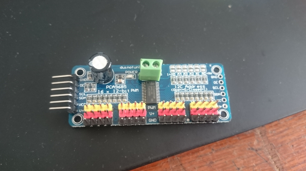
以下摘录官方文档,版权信息
© Adafruit Industries https://learn.adafruit.com/adafruit-16-channel-pwm-slash-servo-shield
Connecting other I2C devices
Since I2C is a 'shared bus' you can still connect other I2C devices to the SDA/SCL pins as long as they do not have a conflicting address. The default address for the shield is address 0x40
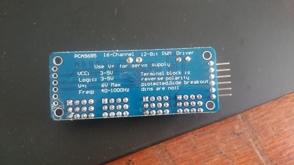
Powering Servos / PWM
This shield has two power supplies. One is VCC - that is the 5V power from the Arduino, it is used to power the PWM chip and determines the I2C logic level and the PWM signal logic level. When this power supply is working you will see a red LED. The red LED must be lit for the Arduino & shield to work! Plug in the Arduino to USB or a wall adapter to provide it.
To power servos you will need to also connect the V+ power supply - this is the power supply for the servos. (If you are lighting up single LEDs you may not need this power supply.) This power supply should be 5 or 6VDC. You can connect this power through the blue terminal block. There is reverse-polarity protection in case you hook up power backwards.
Nearly all servos are designed to run on about 5 or 6v. Keep in mind that a lot of servos moving at the same time (particularly large powerful ones) will need a lot of current. Even micro servos will draw several hundred mA when moving. Some High-torque servos will draw more than 1A each under load.
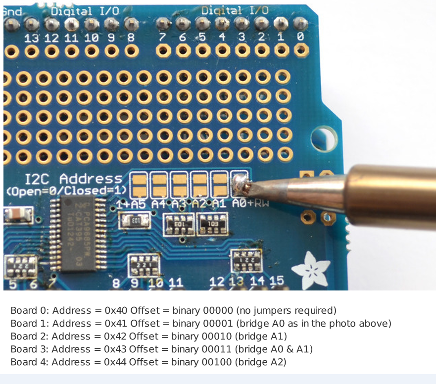
Addressing the Shields
Each board in the chain must be assigned a unique address. This is done with the address jumpers on the upper right edge of the board. The I2C base address for each board is 0x40. The binary address that you program with the address jumpers is added to the base I2C address.
To program the address offset, use a drop of solder to bridge the corresponding address jumper for each binary '1' in the address.
Using the Adafruit Library
Download the library from Github Start by downloading the library from https://github.com/adafruit/Adafruit-PWM-ServoDriver-Library (http://adafru.it/aQl)-
you can just click the button below
Copy the zip file to the Libraries folder inside your Arduino Sketchbook folder and re-name it to Adafruit_PWMServoDriver. For more details on how to install Arduino libraries, check out our detailed tutorial! (http://adafru.it/aYM)
Download Adafruit PWM/Servo Library:
http://adafru.it/cDw
Test with the Example Code:
First make sure all copies of the Arduino are closed.
Next open a new copy of the IDE and select File->Examples>Adafruit_PWMServoDriver->Servo. This will open the example file in an IDE window.
Plug the shield into your Arduino, and a servo into the left-most 'port' as shown on the previous page and upload the example code. Don't forget you will also have to provide 5V to the V+ terminal block. Both red and green LEDs must be lit.
You should see the servo sweep back and forth over approximately 180 degrees. Calibrating your Servos Servo pulse timing varies between different brands and models. Since it is an analog control circuit, there is often some variation between samples of the same brand and model. For precise position control, you will want to calibrate the minumum and maximum pulse-widths in your code to match known positions of the servo.
Find the MInimum: Using the example code, edit SERVOMIN until the low-point of the sweep reaches the minimum range of travel. It is best to approach this gradually and stop before the physical limit of travel is reached.
Find the Maximum: Again using the example code, edit SERVOMAX until the high-point of the sweep reaches the maximum range of travel. Again, is best to approach this gradually and stop before the physical limit of travel is reached.
Converting from Degrees to Pulse Length The Arduino "map()" function (http://adafru.it/aQm) is an easy way to convert between degrees of rotation and your calibrated SERVOMIN and SERVOMAX pulse lengths. Assuming a typical servo with 180 degrees of rotation; once you have calibrated SERVOMIN to the 0degree position and SERVOMAX to the 180 degree position, you can convert any angle between 0 and 180 degrees to the corresponding pulse length with the following line of code:
pulselength = map(degrees, 0, 180, SERVOMIN, SERVOMAX);
转换角度和脉冲之间的关系可以使用奇技淫巧:
pulselength = map(degrees, 0, 180, SERVOMIN, SERVOMAX);
官方示例代码
© Adafruit Industries https://learn.adafruit.com/adafruit-16-channel-pwm-slash-servo-shield
/***************************************************
  This is an example for our Adafruit 16-channel PWM & Servo driver
  Servo test - this will drive 16 servos, one after the other

  Pick one up today in the adafruit shop!
  ------> http://www.adafruit.com/products/815

  These displays use I2C to communicate, 2 pins are required to
  interface. For Arduino UNOs, thats SCL -> Analog 5, SDA -> Analog 4

  Adafruit invests time and resources providing this open source code,
  please support Adafruit and open-source hardware by purchasing
  products from Adafruit!

  Written by Limor Fried/Ladyada for Adafruit Industries.
  BSD license, all text above must be included in any redistribution
 ****************************************************/

#include <Wire.h>
#include <Adafruit_PWMServoDriver.h>

// called this way, it uses the default address 0x40
Adafruit_PWMServoDriver pwm = Adafruit_PWMServoDriver();
// you can also call it with a different address you want
//Adafruit_PWMServoDriver pwm = Adafruit_PWMServoDriver(0x41);

// Depending on your servo make, the pulse width min and max may vary, you
// want these to be as small/large as possible without hitting the hard stop
// for max range. You'll have to tweak them as necessary to match the servos you
// have!
#define SERVOMIN  150 // this is the 'minimum' pulse length count (out of 4096)
#define SERVOMAX  600 // this is the 'maximum' pulse length count (out of 4096)

// our servo # counter
uint8_t servonum = 0;

void setup() {
  Serial.begin(9600);
  Serial.println("16 channel Servo test!");

  pwm.begin();

  pwm.setPWMFreq(60);  // Analog servos run at ~60 Hz updates

  yield();
}

// you can use this function if you'd like to set the pulse length in seconds
// e.g. setServoPulse(0, 0.001) is a ~1 millisecond pulse width. its not precise!
void setServoPulse(uint8_t n, double pulse) {
  double pulselength;

  pulselength = 1000000;   // 1,000,000 us per second
  pulselength /= 60;   // 60 Hz
  Serial.print(pulselength); Serial.println(" us per period");
  pulselength /= 4096;  // 12 bits of resolution
  Serial.print(pulselength); Serial.println(" us per bit");
  pulse *= 1000;
  pulse /= pulselength;
  Serial.println(pulse);
  pwm.setPWM(n, 0, pulse);
}

void loop() {
  // Drive each servo one at a time
  Serial.println(servonum);
  for (uint16_t pulselen = SERVOMIN; pulselen < SERVOMAX; pulselen++) {
    pwm.setPWM(servonum, 0, pulselen);
  }

  delay(500);
  for (uint16_t pulselen = SERVOMAX; pulselen > SERVOMIN; pulselen--) {
    pwm.setPWM(servonum, 0, pulselen);
  }

  delay(500);

  servonum ++;
  if (servonum > 7) servonum = 0;
}
我连了以下。默认的60Hz我的sg90小舵机会抖个不停。50Hz的比较理想。
连接效果:
然而官网上的效果图比较酷炫


洋玩意儿看着真新鲜!!!
@brotherbiao 牛逼啊,洋玩意儿狠