动手做!基于nRF24L01P的Arduino无线通信笔记。nRF24L01P是一种容易获得的、可接受的无线通信解决方案,在热门硬件上有可直接使用的库,可方便快速地应用于方案原型中。
关键词:nRF24L01+ , Arduino , 无线通信
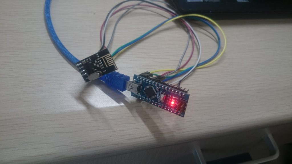
Table of Contents
0.序言
为了帮小崔的毕设解决nRF24L01P的实际使用问题,同时自己也有无线通信的需求(想做一个通用的无线文本显示屏),所以写了这篇记录文章。
1.购买
请注意!一定要根据项目的实际需求,购买价格合理、质量可靠的nRF24L01+。一方面买来的模块直接影响无线传输的速率和丢包率,另一方面,买来的东西要是不好用会直接影响项目的进度和心情的!
这里先记一下我的一次脑抽经历……没时间看的就直接往下拖或者点目录跳过吧
我第一次购买nRF24L01P模块时候是在淘宝上随便搜的,一看,这家店铺牛逼啊!然后一秒下单就不管了。
结果我收到货:
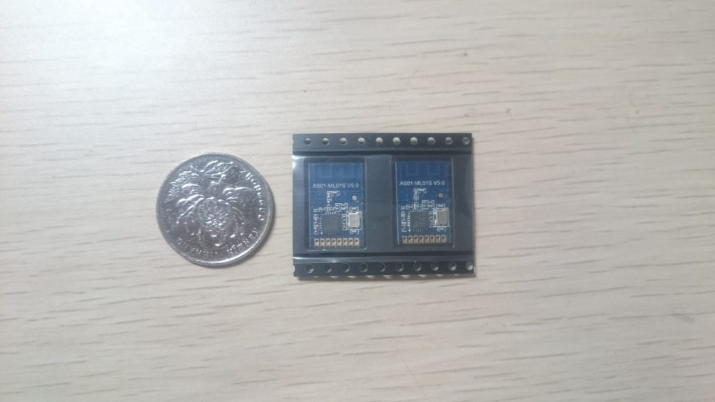
我靠这贴片的尺寸和我想象中的不太一样啊,震惊!然而我没有相应的转接排针
然后我花了整整一晚上的时间:
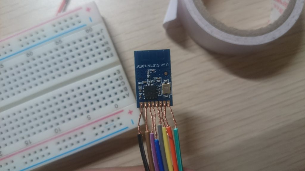
这玩意这尺寸没法用焊锡什么的……自己的锅自己背吧……
更令我震惊的是,在接下来的例程中,竟然连接正常 = =。不过因为短接的关系,大概不到10分钟它们就烧片阵亡了。。。RIP
所以一定要确认好排针的间距,还有模块的质量(这个也很重要!)
最后还是重新淘宝了新的。
2.软件准备
我使用的库是:
https://github.com/nRF24/RF24
star数800+,支持Python、C++(Arduino和树莓派)。
3.硬件相关
看一下定义
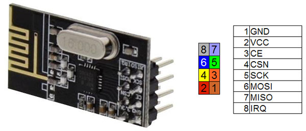
图片取自 http://www.fabacademy.org/archives/2015/eu/students/ciurnelli.mattia/exercise13.html
与板子连接
转自 http://tmrh20.github.io/RF24/
The table below shows how to connect the the pins of the NRF24L01(+) to different boards. CE and CSN are configurable.
| PIN | NRF24L01 | Arduino UNO | ATtiny25/45/85 [0] | ATtiny44/84 [1] | LittleWire [2] | RPI | RPi -P1 Connector |
|---|---|---|---|---|---|---|---|
| 1 | GND | GND | pin 4 | pin 14 | GND | rpi-gnd | (25) |
| 2 | VCC | 3.3V | pin 8 | pin 1 | regulator 3.3V required | rpi-3v3 | (17) |
| 3 | CE | digIO 7(可更改) | pin 2 | pin 12 | pin to 3.3V | rpi-gpio22 | (15) |
| 4 | CSN | digIO 8(可更改) | pin 3 | pin 11 | RESET | rpi-gpio8 | (24) |
| 5 | SCK | digIO 13 | pin 7 | pin 9 | SCK | rpi-sckl | (23) |
| 6 | MOSI | digIO 11 | pin 6 | pin 7 | MOSI | rpi-mosi | (19) |
| 7 | MISO | digIO 12 | pin 5 | pin 8 | MISO | rpi-miso | (21) |
| 8 | IRQ | -(悬空即可) | - | - | - | - | - |
对于Arduino Nano型号的板子,其接线方法与UNO相同。其他板子需要查询SPI定义确认一下。
必须注意的是,RF24这个芯片必须接3.3V,接5V将立刻烧毁。切记切记!
接线后如图
4.软件使用
4.1 getstarted
用了大受欢迎的RF24的库,先使用getstarted的例程
/*
* Getting Started example sketch for nRF24L01+ radios
* This is a very basic example of how to send data from one node to another
* Updated: Dec 2014 by TMRh20
*/

#include <SPI.h>
#include "RF24.h"

/****************** User Config ***************************/
/***      Set this radio as radio number 0 or 1         ***/
bool radioNumber = 0;

/* Hardware configuration: Set up nRF24L01 radio on SPI bus plus pins 7 & 8 */
RF24 radio(7,8);
/**********************************************************/

byte addresses[][6] = {"1Node","2Node"};

// Used to control whether this node is sending or receiving
bool role = 0;

void setup() {
  Serial.begin(115200);
  Serial.println(F("RF24/examples/GettingStarted"));
  Serial.println(F("*** PRESS 'T' to begin transmitting to the other node"));

  radio.begin();

  // Set the PA Level low to prevent power supply related issues since this is a
 // getting_started sketch, and the likelihood of close proximity of the devices. RF24_PA_MAX is default.
  radio.setPALevel(RF24_PA_LOW);

  // Open a writing and reading pipe on each radio, with opposite addresses
  if(radioNumber){
    radio.openWritingPipe(addresses[1]);
    radio.openReadingPipe(1,addresses[0]);
  }else{
    radio.openWritingPipe(addresses[0]);
    radio.openReadingPipe(1,addresses[1]);
  }

  // Start the radio listening for data
  radio.startListening();
}

void loop() {


/****************** Ping Out Role ***************************/
if (role == 1)  {

    radio.stopListening();                                    // First, stop listening so we can talk.


    Serial.println(F("Now sending"));

    unsigned long start_time = micros();                             // Take the time, and send it.  This will block until complete
     if (!radio.write( &start_time, sizeof(unsigned long) )){
       Serial.println(F("failed"));
     }

    radio.startListening();                                    // Now, continue listening

    unsigned long started_waiting_at = micros();               // Set up a timeout period, get the current microseconds
    boolean timeout = false;                                   // Set up a variable to indicate if a response was received or not

    while ( ! radio.available() ){                             // While nothing is received
      if (micros() - started_waiting_at > 200000 ){            // If waited longer than 200ms, indicate timeout and exit while loop
          timeout = true;
          break;
      }
    }

    if ( timeout ){                                             // Describe the results
        Serial.println(F("Failed, response timed out."));
    }else{
        unsigned long got_time;                                 // Grab the response, compare, and send to debugging spew
        radio.read( &got_time, sizeof(unsigned long) );
        unsigned long end_time = micros();

        // Spew it
        Serial.print(F("Sent "));
        Serial.print(start_time);
        Serial.print(F(", Got response "));
        Serial.print(got_time);
        Serial.print(F(", Round-trip delay "));
        Serial.print(end_time-start_time);
        Serial.println(F(" microseconds"));
    }

    // Try again 1s later
    delay(1000);
  }


/****************** Pong Back Role ***************************/

  if ( role == 0 )
  {
    unsigned long got_time;

    if( radio.available()){
                                                                    // Variable for the received timestamp
      while (radio.available()) {                                   // While there is data ready
        radio.read( &got_time, sizeof(unsigned long) );             // Get the payload
      }

      radio.stopListening();                                        // First, stop listening so we can talk
      radio.write( &got_time, sizeof(unsigned long) );              // Send the final one back.
      radio.startListening();                                       // Now, resume listening so we catch the next packets.
      Serial.print(F("Sent response "));
      Serial.println(got_time);
   }
 }


/****************** Change Roles via Serial Commands ***************************/

  if ( Serial.available() )
  {
    char c = toupper(Serial.read());
    if ( c == 'T' && role == 0 ){
      Serial.println(F("*** CHANGING TO TRANSMIT ROLE -- PRESS 'R' TO SWITCH BACK"));
      role = 1;                  // Become the primary transmitter (ping out)

   }else
    if ( c == 'R' && role == 1 ){
      Serial.println(F("*** CHANGING TO RECEIVE ROLE -- PRESS 'T' TO SWITCH BACK"));
       role = 0;                // Become the primary receiver (pong back)
       radio.startListening();

    }
  }


} // Loop
注意,使用两个Arduino,每个的通信地址需要不同,每个烧录时使用不同的地址,改动初始化的radioNumber一个为1一个为0,其它不用变,烧进去。
bool radioNumber = 0;
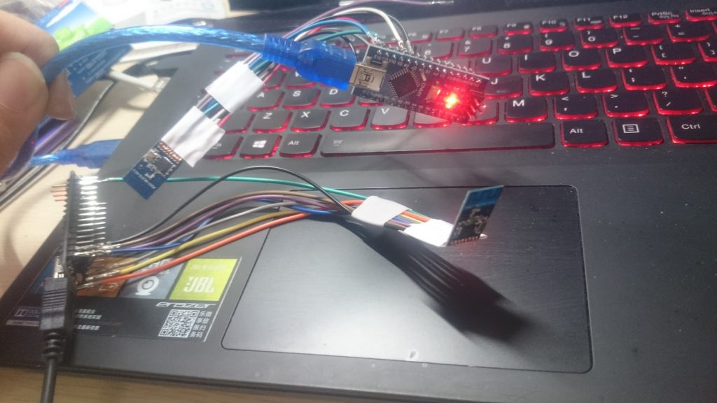
两个都通电后,打开发射端的串口监视器,发送一个T即可开始传输。效果如下
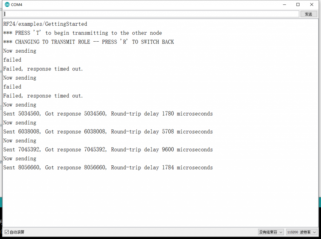 不过我的丢包率有点高啊,可能是买的廉价货的原因。
之前小崔一直实验失败,可能是其接触不良或者面包板的问题。请大家一定不要吝啬,买质量好的线材和元件。
对于一些需求和稳定性的修正,要看一下所有例程,简单看一下注释即可


[…] 2017-04-19 动手做!基于nRF24L01P的Arduino无线通信 […]
这是ardino 的板子
@小路玩 对的。文章中用的是Arduino Nano
各种看不懂,因为我没玩过树莓派。